Difference between revisions of "Westerly 22 rudder design"
(→Westerly 22 rudder design) |
(→Westerly 22 rudder design) |
||
| Line 15: | Line 15: | ||
====Drawings==== | ====Drawings==== | ||
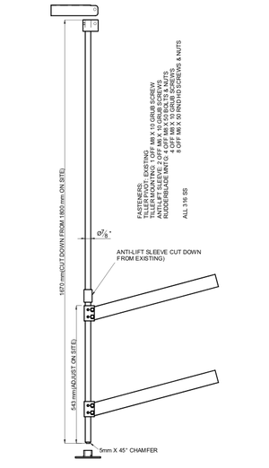
| + | Fig 1 shows the complete system put together. One could possibly skip the anti-lift ring as the weight of the construction has never lifted the rudder bar out of the existing (40 year old) heel bearing in the past 3 years. | ||
| + | [[File:P1 assembly.png|thumb|none|alt=rudder assembly|Fig 1. The rudder assembly]] | ||
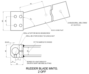
| + | The actual rudder blade was cut out of 2.5cm marine ply (no dimensions available) and covered in expoxy (see Fig 2). | ||
| + | |||
| + | [[File:P2 blade mntg.png|thumb|none|alt=blade mounting|Fig 2. Rudder blade mounting]] | ||
| + | |||
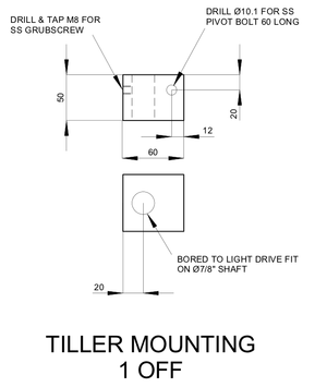
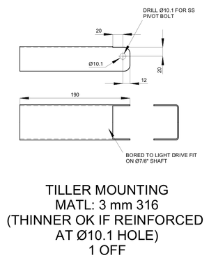
| + | The tiller mounting was welded on top of the rudder bar. Over it will fit the tiller pivot mounting (see Fig 4). | ||
| + | |||
| + | [[File:P3 tiller mounting.png|thumb|none|alt=tiller mounting|Fig 3. Tiller mounting]] | ||
| + | |||
| + | [[File:P4 tiller pivot.png|thumb|none|alt=tiller pivot|Fig 4. Tiller pivot mounting]] | ||
| + | |||
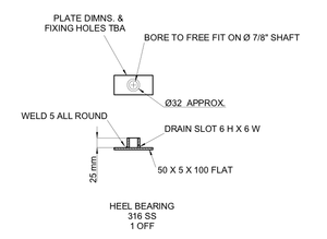
| + | The rudder bar heel bearing was designed but never fitted as the new stainless steel rudder bar fitted well in the existing socket mounted on the skeg. | ||
| + | [[File:P5 heel bearing.png|thumb|none|alt=heel bearing|Fig 5. Rudder bar heel bearing]] | ||
Revision as of 22:29, 9 May 2012
Westerly 22 rudder design
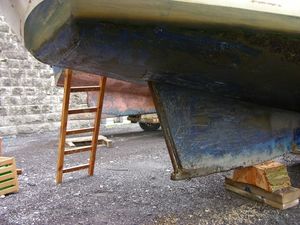
In the spring of 2009 our Westerly 22 lost its rudder to drying out on a very uneven sandbank in very uneven weather. Luckily with the outboard is was still possible to steer her to the lift out position. At the spring lift out it was obvious even to an inexperienced sailer that a crucial part was missing. The steel rudder bar had also been eaten away over the years at the water line.
Welding a new rudder blade onto the existing rudder bar was unlikely to produce a a strong construction due to the lack proper access. It was decided the new rudder had to
- be a stainless steel construction
- be mountable in situ at the drying mooring
Being part of a fantastically supportive sailing community, a fellow sailer offered to get a new rudder designed and build. The following drawings were made by Terry McMennamim for which I am very greatful.
The design is such that the stainless steel rudder bar slides in from the top through the rudder blade mountings. The rudder is then fixed to the bar by tightening the clamp construction and inserting grub screws.
Drawings
Fig 1 shows the complete system put together. One could possibly skip the anti-lift ring as the weight of the construction has never lifted the rudder bar out of the existing (40 year old) heel bearing in the past 3 years.
The actual rudder blade was cut out of 2.5cm marine ply (no dimensions available) and covered in expoxy (see Fig 2).
The tiller mounting was welded on top of the rudder bar. Over it will fit the tiller pivot mounting (see Fig 4).
The rudder bar heel bearing was designed but never fitted as the new stainless steel rudder bar fitted well in the existing socket mounted on the skeg.
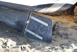
Final result
The final construction looks like this.
