Installation of shore power connection and battery charger
The Task
One of the reasons why we bought "Periplus" in January 2020 was the fact that we were able to buy the boat from the original owner, who had kept her well maintained and in good condition but had made virtually no changes to the original equipment. So, in January 2020, the boat presented herself more or less as she had when she was launched in January 1989: no refrigeration unit, no running water, no anchor windlass, no shore power connection, no battery charger, no dinghy, no life raft...
The boat was well maintained and in good condition, but no one had yet realized their ideas about what "absolutely had to be added". This means that we could and still can develop our own ideas of "necessary additions" without first having to dismantle any undesirable former developments; and we resolved that we would proceed very conservatively and only reach for the drill and saw when we were sure that we had a real improvement in mind that would stand the test of time. That's why, almost three years on, there's still no refrigeration unit, no running water, no anchor windlass, no life raft... but we do now have a dinghy and a shore power connection with battery charger. I would like to tell you a few things about the latter here.
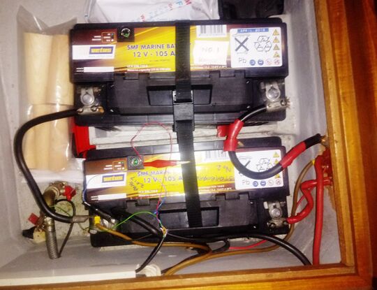
Again, the pre-purchase surveyor had some advice for us: "It is advised that the owner may wish to consider re-wiring the batteries such that one battery is dedicated to engine starting and the other for domestic and navigation equipment." This means that the two batteries, which are identical in construction, were connected in such a way that each of them could work both as a starter battery and as a domestic battery. If necessary, for example when charging, both batteries could also be connected in parallel. On the other hand, there was a cable about 25 m long that could be used to bring shore power on board. This ended in a British socket, to which we had connected a power distributor via an adapter... Using an external charger, we could also charge the batteries with the help of this "shore power connection" when we were in a marina. Yet the circuits were not separate, even though the batteries could be switched on separately.
Original setup
The Solution
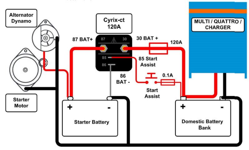
A cable connection in the cockpit should be followed by a galvanic separation and a circuit breaker. There, the 230 V range should be divided: one connection for the charger and at least one connection for a 230 V socket in the salon. After we had procured a Victron Energy Blue Smart IP22 charger with 20A and three charging connections, as well as a Victron Energy Cyrix-ct battery coupler, our wiring diagram would look something like this:
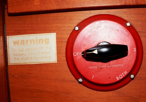
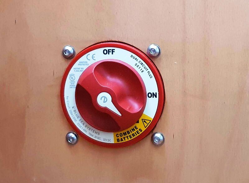
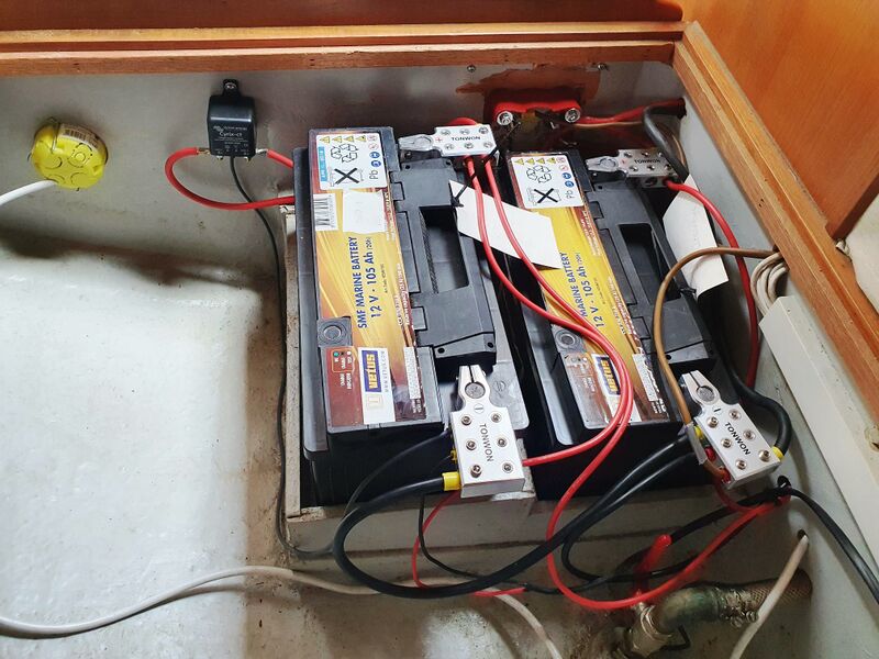
Connecting a "start-assist" would not be necessary because we also wanted to install a new main battery switch that could switch both circuits separately but simultaneously. This also has a possibility to switch both batteries in parallel in case of emergency. A fixed connection for the shore power cable was to be installed in the cockpit area, with which we can also supply a permanent 230 V AC connection in the salon, this time with two European “Schuko” sockets. In order for the whole thing to meet current standards, we also needed a galvanic separation of the protective contact to save our zinc anodes, as well as a fuse and circuit breaker to provide appropriate protection for the high-voltage side of the installation. Since the current battery connections could no longer accommodate the many new cables, new battery connections also had to be procured; each of these can now accommodate up to six cables.
The Implementation
We spent a lot of time thinking about where we wanted to place the new connections and devices and where in the cockpit we should mount the new socket so that it would be easy to reach on the one hand and as little in the way as possible on the other - both when the cable is connected and while sailing.
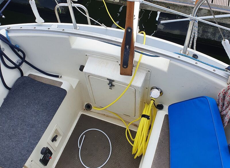
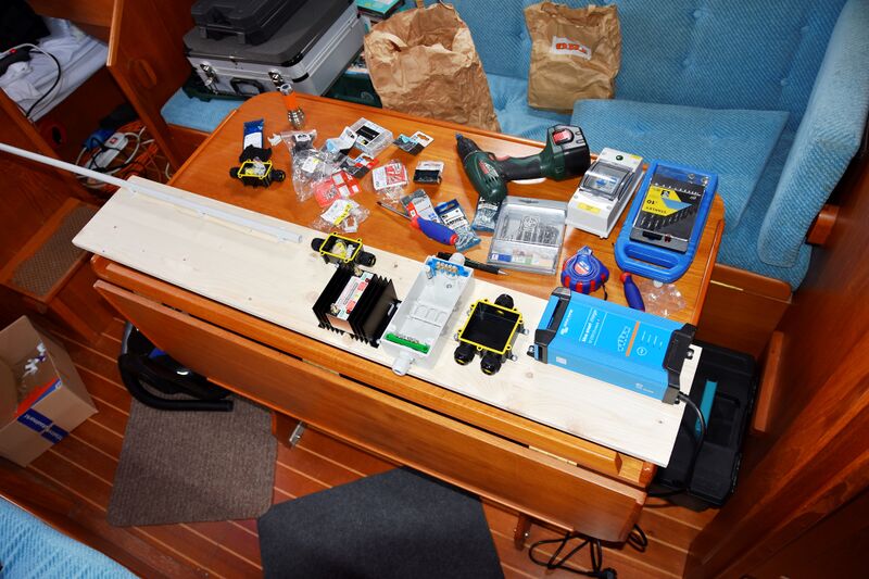
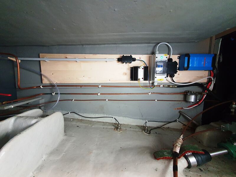
The cable connection was finally mounted at the rear of the cockpit, slightly above the seat and to the right of the compartment for the gas bottle. So far, this works very well. When placing the charger, it was also important that there is enough air for the cooling to work effectively. Since there would hardly be any simultaneous operation of the engine if the charger worked via the shore connection, we decided to mount the galvanic isolation, the circuit breaker and the charger on a common board mounted above the diesel lines in the engine compartment. The board is screwed to the port side of the engine compartment from the aft berth, the supply line is led via a mounting pipe from the stern. In this way, all the leads are made as short as possible, both from the socket to the mounting board and from the charger to the battery area.
Since we want to sail as well as work in the limited time we can spend on the boat, we have done the whole business in two stages. In spring 22 we finished the cockpit socket and the 230 V side of the installation, and in the autumn during our "working visit" we completed the connection of the new main switch, the battery coupler and the batteries. As the boat was on land during this, we have not yet been able to test charging via the engine; this will not be possible until next spring.
Edit: In the meantime, we have made our springtime cruise in the Netherlands. During our few days on Vlieland we did not connect to the shore power but used the service battery. During the day, we lit some navigational lights in order to use more power so that we could see a difference in the voltage of our two batteries. After almost 48 hours, the service battery has used up quite a bit of its capacity, whereas the starter battery has remained full. The battery coupler has prevented the unused starter battery to unload into the used domestic battery. As soon as we started the engine, both batteries got loaded.
Resume
The surveyor's recommendation to make separate circuits for the starter and service batteries has now been implemented. At the same time, we have made a fixed connection for 230 V in the cockpit, which also allows us to have two proper power connections for 230 V in the saloon when we are moored with our "pepperbird" in a marina. The charger would thereby charge our batteries in the marina in an appropriately save manner, and in engine mode the electronic battery coupler would ensure that both batteries are charged via the alternator. By placing the new devices in the engine compartment and by the discreet and noble design of the cable connection, we have managed to do this with minimal impact to the appearance of the boat, both in the cockpit and in the salon.
Images
In the cockpit
Setting up the mounting board
Installation in the engine compartment
New Main switch
New battery setup
Otto Hollerwöger
KT653
Fin keeled Konsort pepperbird aka Periplus
